Basic connected with the wrist assembly:
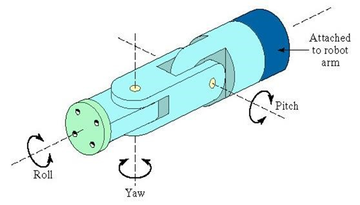
- Wrist assembly is attached to end-of-arm
- End effector is attached to wrist assembly
- Function of wrist assembly is to orient end-effector
- Body-and-arm determines global position of end effector
- Two or three degrees of freedom are normally used:
- Roll
- Pitch
- Yaw
With end of arm tooling we can consider the following:
- The most essential part of robot is for determining its functionality is end effector, or end-of-arm-tooling (EOT). There are very different application for EOT. Most common are end effectors including welding devices (MIG, TIG welding, spot welding), spry guns also grinding and deburring devices (pneumatic disk or belt grinders); grippers (devices that can grip an object, usually electromechanical or pneumatic); picking objects by vacuum; EOT devices for machining, etc.
- EOT are frequently highly complex. They can carry out different activities at the same time and may utilize various sensors.
End-effector systems are rapidly in developing
4.2 Basic Classification of End Effectors
End effectors are the last part of a robot arm. They are directly connected to the wrist and have two basic functions: to grasp the objects or to do the work with the objects. For grasping are used different grippers. For doing the work (welding, painting, grinding, polishing, etc.) are used different tools. This have a general meaning as End of Arm Tooling, which is used sometimes also as a general meaning of end effectors.
4.2.1 Grippers
Mechanical grippers
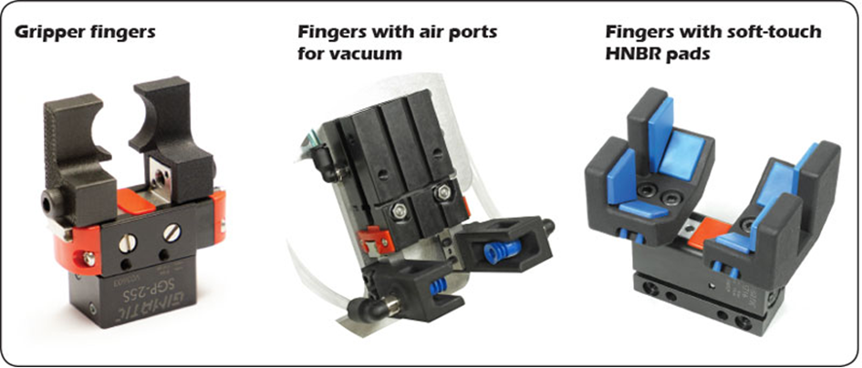
Mechanical grippers are grippers that use mechanical fingers to manipulate objects (see Fig.5). Mechanical grippers have a distinctive design that is reminiscent of a crab’s pincers. Mechanical grippers usually come with adjustable force and stroke features, enabling them to perform tasks with human-like precision and dexterity. The number of robot fingers vary depending on the model; however, most mechanical grippers have two to four fingers. The fingers are per default replaceable, allowing you to make the most of your investment.
Grippers grasp and manipulate objects during the work cycle. Typically the objects grasped are workpieces that need to be loaded or unloaded. The loading unloading tasks depend from industrial task. It could be realised based on one equipment or for replacing the object from one station to another. Typical loading-unloading operations are machine tool tending, execution of bending, pressing, etc operations, using for pick and place or palletizing activities. Grippers may be standardized or custom-designed to suit the physical specifications of the workpieces they have to grasp. Basic classification of grippers are given in a Table 1.
Different applications of mechanical grippers are given in Fig.5 and 6.
Table 1 End effectors – grippers basic classification
| Type | Description |
| Mechanical gripper | Two or more fingers that can be actuated by robot controller to open and close on a workpiece |
| Vacuum gripper | Suction cups are used to hold flat objects |
| Magnetised devices | Making use of the principles of magnetism, these are used for holding ferrous workpieces |
| Adhesive devices | Deploying adhesive substances these hold flexible materials, such as fabric |
| Simple mechanical devices | For example, hooks and scoops |
| Dual grippers | Mechanical gripper with two gripping devices in one end effector for machine loading and unloading. Reduces cycle time per part by gripping two workpieces at the same time |
| Interchangeable fingers | Mechanical gripper whereby, to accommodate different workpiece sizes, different fingers may be attached |
| Sensory feedback fingers | Mechanical gripper with sensory feedback capabilities in the fingers to aid locating the workpiece; and to determine correct grip force to apply (for fragile workpieces) |
| Multiple fingered grippers | Mechanical gripper with the general anatomy of the human hand. Standard grippers |
| Standard grippers | Mechanical grippers that are commercially available, thus reducing the need to custom-design a gripper for each separate robot application |

End effector for machine tending is give in the Figure 7.
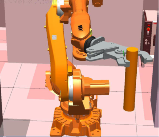
There is also a significant problem to choose the right end effector. First it is necessary to take care of the needed functionality. For loading unloading operations there is needed to grasp the object. There is also needed to consider the measures of servicing objects, also the weight. Very important is to understand about the material of the objects, their surface quality conditions and other specific issues. For sheet metal products producing operations vacuum grippers are widely used.
Some parameters of grippers for palletizing operations are given in the Figure 8.

Technical Parameters
| Gripper type | Clamp (Single zone) | Clamp (Double zone) | Claw | Vacuum |
| Gripper weight (kg) | 45 | 80 | 60 | 75 |
| Max weight / lift (kg) | 40 | 60 | 50 | 40 |
| Product type | Case | Case | Bag | Case, pallet |
Figure 8. Grippers for palletizing
There is necessary to consider that the end-effectors are working also together with the industrial robots. And the robot parameters and their functionality must fit to the parameters of end effectors.
Vacuum grippers
Vacuum grippers provide gripping through suction cups and are mostly used for handling workpieces with uneven surfaces or irregular shapes. Traditional vacuum grippers utilize external air supply systems which require high maintenance costs. Newer models run on electricity instead, eliminating the heavy costs in addition to improving the work environment due to producing less noise and dust. One example (see Fig.9) VG10 vacuum gripper falls into the latter category.

Adhesive grippers
These types of grippers grasp objects by sticking to them instead of holding them (see Fig.10). Adhesive grippers are typically used to pick up light-weight objects, such as fabrics. However, the reliability of an adhesive gripper will diminish with each successful operation due the adhesive substance losing its quality.
Grippers can grasp work pieces, centre and orientated them. It should include sensors to indicate, if a part is present or not. On the whole a gripper should be as lightweight as possible, for the maximum payload of a machine includes the weight of a work piece. Housing and fork should be held as close to the axis of grip as possible, so as to avoid high moments on the gripper.
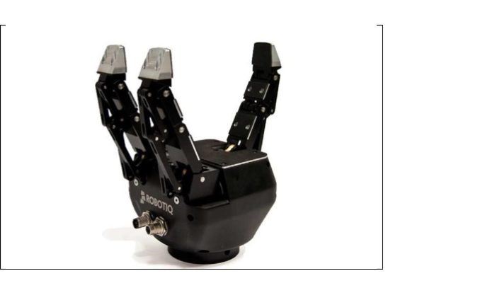
The above shown three finger gripper is an adequate end effector for performing task of taking parts from input buffer and put them into the servicing machine and then take them out and keep them to output buffer.
The robotic grippers could be classified also according to the working principles: vacuum grippers, pneumatic grippers, hydraulic grippers and servo-electric grippers. Manufacturers choose grippers based on which handling application is required and the type of material in use.
Vacuum Grippers
The vacuum gripper has been the standard EOAT in manufacturing because of its high level of flexibility. This type of robot gripper uses a rubber or polyurethane suction cup to pick up items. Some vacuum grippers use a closed-cell foam rubber layer, rather than suction cups, to complete the application.
Pneumatic Grippers
The pneumatic gripper is popular due to its compact size and light weight. It can easily be incorporated into tight spaces, which can be helpful in the manufacturing industry. Pneumatic robot grippers can either be opened or closed, earning them the nickname “bang bang” actuators, because of the noise created when the metal-on-metal gripper operates.
Hydraulic Grippers
The hydraulic gripper provides the most strength and is often used for applications that require significant amounts of force. These robotic grippers generate their strength from pumps that can provide up to 2000psi. Although they are strong, hydraulic grippers are messier than other grippers due to the oil used in the pumps. They also may need more maintenance due the gripper being damaged because of the force used during the application.
Servo-Electric Grippers
The servo-electric gripper appears more and more in industrial settings, due to the fact that it is easy to control. Electronic motors control the movement of the gripper jaws. These grippers are highly flexible and allow for different material tolerances when handling parts. Servo-electric grippers are also cost effective because they are clean and have no air lines.
4.3 End of Arm Tooling
Additionally to material handling industrial robots are being used in three types of applications: processing operations; assembly and inspection. In processing operations the robot performs some processing actions, such as grinding, milling, machining etc. on the workpiece. The end effector is equipped with the specialised tool required for the process, and the tool is moved relative to the surface of the workpiece. Table 2 outlines examples of processing operations that deploy robots. Welding (arc welding or spot welding is one of the most popular application area of industrial robots. The application areas of EOAT is given in the Table 2
Table 2. Industrial robot applications
| Process | Description |
| Spot Welding | Metal joining process in which two sheet metal parts are fused together at localised points of contact by the deployment of two electrodes that squeeze the metal together and apply an electric current. The electrodes constitute the spot welding gun, which is the end effector tool of the welding robot |
| Arc Welding | Metal joining process that utilises a continuous rather than contact welding point process, in the same way as above. Again the end effector is the electrodes used to achieve the welding arc. The robot must use continuous path control, and a jointed arm robot consisting of six joints is frequently used. |
| Spray Coating | Spray coating directs a spray gun at the object to be coated. Paint or some other fluid flows through the nozzle of the spray gun, which is the end effector, and is dispersed and applied over the surface of the object. Again the robot must use continuous path control, and is typically programmed using manual lead-through. Jointed arm robots seem to be the most common anatomy for this application |
| Other applications | Other applications include: drilling, routing, and other machining processes; grinding, wire brushing, and similar operations; waterjet cutting; and laser cutting. |
The robot end effector may also use tools (in Fig.11 for example grinding tools). Tools are used to perform processing operations (drilling, milling, painting, polishing, etc) on the workpiece. Typically the robot uses the tool relative to a stationary or slowly-moving object; in this way the process is carried out. For example, spot welding, arc welding, and spray painting – these all use a tool for processing the operation. Other examples where a tool is held by the robotic manipulator, and used against the workpiece include: rotating spindle for drilling, routing, grinding, and similar operations. The end effector could also be used as a heating torch or as a water jet cutting tool for cutting operations. Also the robot tool could be used for painting operations, etc. For each instance, the robot controls both the position of the workpiece, and the position of the tool relative to the workpiece. In these cases the robot must be able to transmit control signals to the tool for starting, stooping, and otherwise regulating the tools actions. In the following figures some end-effectors and their use is illustrated.
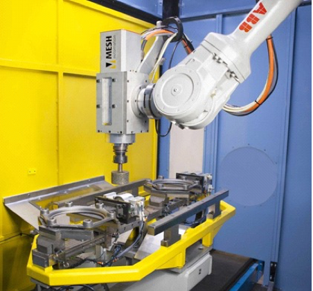
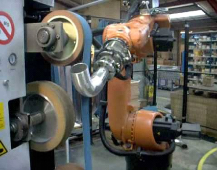
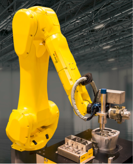
Robot welding is quite widely used application area in the industry. There are different producers who are offering a wide range of welding robots: ABB, Motoman-Yashkawa, Fanuc, etc. Here we a giving some examples for describing EOAT for welding operations.
The FlexGun is a linear spot welding gun was selected for the case of spot welding, The FlexGun is a servo controlled spot welding gun. When attached to the ABB robot it act as a 7th axis offering improved welding quality and cycle time performance. The FlexGun is also robust and able to produce high forces at the electrode tips for welding of high strength steels (see Fig 12).
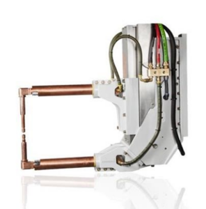
Figure 12. ABB FlexGun for Spot Welding
There are different selection criteria for decision making. In the following some of them are described. In regards to Arc welding for example the Aristo RT2 Torch is described. This tool could be attached to the Arc welding robot (ABB IRB 4600). It was selected because it is very suitable for arc welding due to its mechanised solution with and air-cooled mechanism. Optimized gas flow provides stable and reliable welding arc. It is also suitable for all kinds of robot’s types and model. The robust brass torch flange and optimized gas flow provides stable and reliable welding arc. One widely used arc welding gun is presented on the Figure 13.
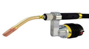
Figure 13. Arc welding gun Aristo RT2 Torch
The importance of this tool selection is tied to so many other important features which includes easy installation, built in blow out port can be used for cooling and/or cleaning of the torch neck and also long-life consumables, torch body, and easy access to spare parts spare parts.
Using EOAT for painting is given in Figure 14.

Figure 14 Paint sprayer is an important part of robots used for painting operations
Looking this small variety of given end-effectors we can see that the construction of these are quite different. Mostly it depends from the application area. The robot grippers usually are built by standard aluminium profiles and this makes them easy-to-design or modify to a low cost. Quick-plug-in contacts for electricity and air makes it easy to change between several grippers. In order to be able to handle perforated sheet and other materials not suitable for the regular vacuum cups, it can be equipped with magnets or gripper fingers instead.
7.4 End- effectors selection principles
Selection on end-effectors is an important task. There is a big number of producers (see Table 1 and APPENDIX 1) and a big number of variants. To have an imagine look for example SCHUNK Gripping Systems.
Table 1 Some producers of end-effectors
|
Producer |
Type of end-effector |
|
Mechanical |
|
Mechanical |
|
Pneumatic |
|
Mechanical |
|
Mechanical |
|
Mechanical / Pneumatic |
|
Pneumatic |
|
Mechanical |
|
Pneumatic |
There are standardized solutions, using usually modular systems and custom made end-effectors for a certain operation in a company.
There are three main steps in the selection process:
STEP 1. Production task description in the robot-cell (understanding about the needs of operation (s))
STEP 2. Industrial robot technological capabilities description (understanding about the execution of the task with the help of robot)
STEP 3. Selection of the end-effector, based on step 1 1nd step 2 and information of the possible end-effector producer (technical information of products)
In step 3 the following information is useful to consider (specially if mechanical grippers)
- Number of clamping elements
- Gripping force (N)
- Weight (kg)
- Recommended workpiece weight (kg)
- Closing/opening time (s)
- Maximum permissible finger length (mm)
- Repeat accuracy (mm)
- Protection class IP
- Cleanroom class ISO 14644-1
- Sensor systems
- Additional description
- Experiences of application
- Exploitation conditions (dust, liquids, aggressive chemicals, temperature limits, cleanroom, etc)
In sheet metal bending, at part is bent using a set of punches and dies. The punch and the die are mounted on a press-brake, which controls the relative motion between the punch and die, and provides the necessary bending pressure. For replacing the manufacturing part different grippers in robot-cells are needed. Mostly vacuum grippers are used. A lot of research is continuously made for designing the bending grippers. For example the users can make bends on three different sides of a part without regripping. Gripper suction cups are controlled via offline software and activated according to part size. Because one gripper fits all applications, production is continuous and uninterrupted [1]. The features of a gripper for the bending operation is extremely important. The construction of a gripper with the suction Cups for Handling Sheet Metal forms the handling device. (https://www.schmalz.com/en/vacuum-technology-for-automation/vacuum-components/vacuum-suction-cups/suction-cups-for-handling-sheet-metal.
The selection of a right gripper for the bending operation is an extremely important task. Some basic ideas for bending operations are given in the short lecture
End of Arm Tooling Organization in a Workplace
Numerical controlled sheet metal flexible bending cell with the robot as the core execution part is a set of highly automated equipment combinations, which has the advantages of high efficiency, high quality and high flexibility.
https://www.machinemfg.com/robotic-press-brake-bending/
Some examples of using end-effectors for bending operations in the company.
Figure 15. The gripper and object for bending
Figure 16. Bending tools ready for use
Conclusion
| Gripper system |
Important topics
|
|---|
The most common purpose of a gripper (sometimes also referred to as an end effector) is to grasp or enclose parts for transfer, insertion, or assembly in automated manufacturing and processing systems. Additionally, grippers are used in environments that are hazardous for human presence. Several factors are required for selection and design to ensure proper gripping. The following considerations will help you in choosing and sizing the right gripper for your application.
- Part Shape – If the product or part has two opposing flats, a 2-jaw gripper is normally used. If the part is cylindrical, a 3-jaw gripper could be used. Tooling can be designed to accommodate cylindrical parts with a 2-jaw gripper.
- Accessibility & Part Consistency – Angular grippers are usually low in cost, but the arcing motion of the jaws may require additional tooling clearance and will grip at varying points as part width varies. A parallel gripper is easier to tool in order to compensate for part size.
- Part Weight – Grip force must be adequate to safely transport the part.
- Orientation & Dimensions – Part orientation and distance from the gripper face affects the gripper selection.
- Size – Nominal gripping dimension indicates approximate gripper size.
- Variation – Variation in gripping location or encapsulation determines minimum gripper jaw travel.
- Air Pressure – The air pressure at the gripper affects gripper sizing and must be taken into account.
- Grip On Open or Close – Grip force varies in each direction due to the effective area of the piston rod on some gripper types. Verify that the gripping direction is taken into account when sizing.
- Velocity – Higher speeds and acceleration/deceleration affects gripper selection.
- Tooling Length – Longer tooling inducts bending moments into the gripper and affects sizing.
- Tooling Configuration – If the part is encapsulated, the required gripping force can be lower than if it is grasped on flats only.
- Product Retention – If part retention upon air loss is desired, springs or locking cams can be specified for the gripper.
- Environment – For harsh environments, special platings or materials should be specified.
- Synchronous Operation – Most grippers provide synchronized jaw movement. In special circumstances, independent jaw travel is desired and can be supplied by request.
- Switching Options – Most grippers offer several switching options.
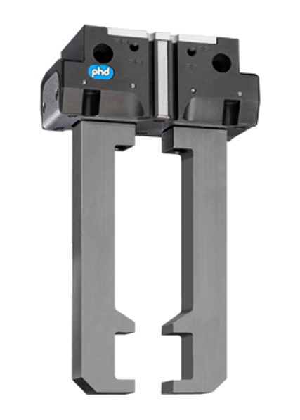
Parallel grippers have their own set of specifications. These include gripping force, stroke and gripping size. Gripping force is the available force for gripping at the rated power. Gripping size is the grip size for actuated gripper. User may specify range. Grippers frequently allow for custom machined fingers or jaws to be attached.
Standards:
BS EN ISO 14539 – MANIPULATING INDUSTRIAL ROBOTS – OBJECT HANDLING WITH GRASP-TYPE GRIPPERS – VOCABULARY AND PRESENTATION OF CHARACTERISTICS
7.5 Gripper selection for packaging
When moving products or packages in an industrial setting, properly matching a robot’s end-of-arm tooling to the materials being moved improves application effectiveness. That may seem like common sense, but hoisting or stacking different materials requires careful consideration of many essential variables to avoid accidents, injuries and downtime.
One of the most common end-of-arm tooling options is the gripper. What is a gripper? Simply stated, a gripper is an interface between a robot or machine and the physical world. A gripper acts on the work piece (product or package), allowing the robot to hold and manipulate it as it performs a series of tasks.
It would require an in-house expert to review every option, setting and scenario of your operations, and how those elements can dictate your choice, but this baseline can give you the tools you need to begin evaluating your pick-and-place needs.
Now, let’s discuss whether mechanical grippers or vacuum grippers are best suited to solve your pick-and-place packaging challenges.
Mechanical grippers
Mechanical grippers use two or more “fingers,” also known as jaws, that close and grip the product or package. They are a cost-effective and reliable option for many standard pick-and-place packaging applications.
A mechanical gripper can maintain a firm hold on products or packages during high-speed movements and their powerful jaws can lift and hold heavy items, but are in danger of crushing delicate items without proper calibration. They can pick and place pieces with varying thickness without changing the gripper, but oddly shaped items may present a challenge to static jaw shapes and angles. Mechanical grippers must operate in the same environment as the work piece, creating potential failure modes, and need enough room for the jaws to actuate. Additional space is necessary to allow it to grip a work piece from multiple sides.
When moving products or packages in an industrial setting, properly matching a robot’s end-of-arm tooling to the materials being moved improves application effectiveness. That may seem like common sense, but hoisting or stacking different materials requires careful consideration of many essential variables to avoid accidents, injuries and downtime.
Mechanical grippers are driven by any of three power sources:
• Pneumatic—Because most plants employ compressed air, pneumatic mechanical grippers are the most common and provide easy implementation, but do not always provide precise control.
• Electric—Electrically driven mechanical grippers provide precise control, but are more expensive and must be contained within a larger package, resulting in challenges to the program or operation.
• Hydraulic—Hydraulic grippers provide high forces and are capable of lifting larger loads, but they are costly to purchase and maintain, and have the potential for fluid leaks.
Mechanical grippers are also available in four different styles:
1. Two-finger (jaw) angular—Easy to apply, capable of picking different sized parts with the same jaw, and moderately priced; require more space than vacuum grippers.
2. Two-finger (jaw) parallel—Versatile, able to pick the outside or inside of a part, suitable for smaller spaces and flexible enough to pick different sized parts with the same jaw; more expensive and may crush softer or more fragile products/packages.
3. Three finger (jaw) parallel—Helpful when proper positioning is required to move the item; requires the product/package to be properly oriented and positioned for secure grip, and can potentially crush delicate work pieces.
4. Two-finger (jaw) locking—Jaws lock when closed and hold parts firm even if power is lost; higher price point and requires more space than vacuum grippers.
Vacuum grippers
Unlike mechanical grippers, which use jaws to grasp and move items, vacuum grippers use soft foam rubber, plastic plenums or vacuum cups to pick up materials without damaging them. They are ideal for applications with extreme weights (very heavy or very light) or delicate work piece materials, where mechanical grip strength is too low to pick pieces or too high and causes damage.
Vacuum grippers are more versatile than their mechanical counterparts. They can adapt to smaller or larger items by adding additional cups or adjusting flow. Mechanical grippers can sometimes cause damage to the items they pick, but vacuum grippers can pick parts that are delicate or thin without causing damage. Vacuum grippers only need access to one side of a item, allowing them to pick products/packages more easily; on the downside, this sacrifices flexibility that could cause the item to drop. Additionally, small dense parts may not offer enough surface area for a vacuum gripper to pick the part.
Vacuum grippers can also be configured specifically for different environments. Vacuum cups are made from a variety of materials that can be compliant with the Food and Drug Administration (FDA) or meet other regulatory requirements. The vacuum pump can be installed away from the pick point to protect it from environmental hazards.
Vacuum grippers rely on either electricity or compressed air for power. Electric vacuum grippers do not require cumbersome or awkward hoses to operate. The downside of this is low flow, which may make the gripper too weak to pick up some items. Compressed air vacuum grippers, on the other hand, can operate with high vacuum levels, enabling them to pick up heavy products/packages and provide greater flow for picking up parts that are porous.
Vacuum grippers have other variables that need to be considered when making a selection. Some grippers rely strictly on vacuum cups or foam pads to operate. Vacuum cups are easy to service and are highly precise in their operations, making it possible to choose ideal pick points on the work piece to prevent damage. They also come in a variety of shapes, sizes and materials that can be suited for most applications.
Vacuum grippers may also be found with foam pads. These can conform to the shape of the product/package and allow picking a variety of items with a single tool. However, they are not as capable of precise placement when compared to suction cups.
Primary considerations in wrist assembly with end of arm tooling selection include:
- Size
- Weight
- Work piece shape
- Access
- Environment
- Work piece material/structure
- Motion
- Speed
